MIL-DTL-28837C
4.7.4.7 Insertion loss. The insertion loss, both reflected and dissipated using the test setup in figure 4 shall be
measured from the LO port to the RF port with a dc current driven into the IF port at the specified level (see 3.1). The
measurement shall be made at the low end, center, and high end or by a sweep frequency method over the specified
frequency range (see 3.1).
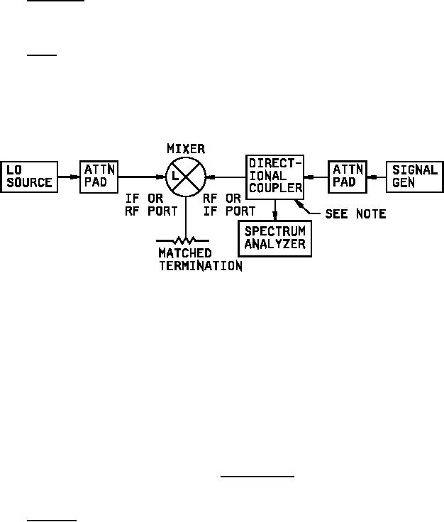
4.7.4.8 VSWR. The VSWR at the RF and IF ports shall be measured using the test setup in figure 8. With the
mixer removed from the test setup, establish a reference level on the spectrum analyzer at the center of the specified
frequency range (see 3.1) by putting a short on the end of the directional coupler. Connect the RF port of the mixer
to the output of the directional coupler. Apply the specified signal (see 3.1) to the LO port. Measure the reflected
power on the spectrum analyzer. Repeat this procedure for the low end and high end of the specified frequency
range (see 3.1). Repeat the procedure at the IF port using the specified IF frequency.
NOTE: The directivity of the directional
coupler shall be such as to permit
measurement of the VSWR with the
appropriate accuracy.
FIGURE 8. VSWR test setup.
4.7.4.9 RF leakage. The RF leakage shall be measured using test set up on figure 9. The test equipment used to
monitor and detect RF leakage shall be calibrated at the center frequency with an input power of 100 mwcw. The
radiated signal strength (see figure 9) shall be measured by placing the antenna horn as close as possible to the
mixer under test without making physical contact. The horn shall be oriented to any direction. The mixer shall be
operated at the calibration power level.
18
For Parts Inquires call Parts Hangar, Inc (727) 493-0744
© Copyright 2015 Integrated Publishing, Inc.
A Service Disabled Veteran Owned Small Business